This post describes the process of fusing the IMU and range data from an OS-1 lidar sensor in order to estimate the odometry of a moving vehicle. The position, orientation, and velocity estimates are critical to enabling high levels of automated behavior such as path planning and obstacle avoidance.
One of the most fundamental methods used by robots for navigation is known as odometry. The goal of odometry is to enable the robot to determine its position in the environment. The position and velocity are determined by measuring the change from the robot’s known initial position using the onboard sensor data.
Sensors are often classified as introspective (relating to, or being stimuli arising within the body) and extrospective (relating to, being, or activated by stimuli received by an organism from outside). Introspective sensors typically measure a vehicle’s velocity or acceleration:
- accelerometer: measures translational acceleration
- gyroscope: measures angular rate
- wheel odometer: measures angular rate
Extrospective sensors measure the position or orientation of the vehicle:
- camera: measures range/bearing to a landmark or landmarks
- time-of-flight sensor: measures range/bearing to a landmark or landmarks
- Global Positioning System: measures absolute position
Sensor fusion is the process of combining sensor data from multiple sensors so that the resulting estimate has less uncertainty than would be possible when these sources were used individually. This is useful when the sensor suite of a mobile robot comprises several different sensors, some complementary and some redundant. Integrating the sensor readings, the robot seeks to accomplish tasks such as estimating its position and velocity.
Each position and velocity estimate is based on the previous estimates so errors are accumulated. The sensors also have sources of error which contribute to errors in the overall odometry estimate. The further the robot travels, the more errors it will accumulate. This differs from localization, which is the determination of the robot’s position relative to known positions of other objects such as landmarks or beacons.
When we combine various sensor measurements into a state estimate, it is important to keep track of all the uncertainties involved and therefore it is hoped to know how confident we can be in our estimate.
Odometry Estimation in Simulation
To simplify the problem and verify the system architecture, we will first compute the odometry in a simulated environment. We will use ROS Gazebo as the simulation environment and visualize the sensor and vehicle state estimation in RViz.
To generate sensor measurements, we will use a simulated OS-1-64 lidar sensor to get IMU and distance measurements. A detailed description of the development of the simulated sensor is available here. The OS-1-64 will be mounted on a simulated RC car provided by the MIT RACECAR project. A simulated GPS sensor will be mounted on the RC car as well to get global position estimates. Lastly, we will use the WillowGarage world as the simulated environment to operate the system and create the map. A sample image of the OS-1-64 mounted on the racecar platform in the WillowGarage Gazebo environment is below:

When working with the RC car, the diy_driverless_car_ROS repository is used. To set-up the simulation, the rc_dbw_walker.launch launch file is executed. This launch file spawns the RC car with the simulated sensors in the WillowGarage environment. It also enables control of the vehicle from the joystick (Xbox controller) or keyboard commands.
The vehicle control nodes are defined in the rc_control_gazebo.launch file. Several nodes are used to prioritize the control inputs between the keyboard or joystick and to convert the commands into the proper message types for input into the Gazebo simulator. Lastly, to generate the odometry estimate, several nodes from the robot_localization package are used.
Robot_localization Package
Since all sensors have limited precision, all measurements derived from the sensor have associated uncertainty. When we use sensor fusion to estimate the state of the vehicle, it is important to account for all the uncertainties involved and the confidence associated with the estimate. The robot_localization package is a collection of state estimation nodes, each of which is an implementation of a nonlinear state estimator for robots moving in 3D space. It contains two state estimation nodes, ekf_localization_node and ukf_localization_node.
These nodes are variant on the Kalman filter. The Kalman filter is a popular tool for combining inaccurate sensor measurements and producing an estimate of the future state of the system. The Kalman filter is intended for linear systems in which the noise can be modeled as a Gaussian distribution. The Kalman filter is known as an “optimal” estimator since it is proven to minimizes the mean square error of the estimated parameters.
The Extended Kalman Filter (EKF) has become a standard formulation for nonlinear state estimation. The EKF uses a Taylor series expansion to linearly approximate a nonlinear function. The EKF linearizes the system under investigation around its current state and forces the filter to use this linearized version of the system as a model.
However, the EKF may cause significant error for highly nonlinear systems because of the propagation of uncertainty through the nonlinear system. In this case, the Unscented Kalman Filter (UKF) is used which uses an Unscented Transform to linearize sampling points (sigma points) around the current state estimate based on its covariance.
The nodes from the robot_localization package are executed in the rc_control_gazebo.launch file. The state estimation nodes of robot_localization produce a state estimate whose pose is given in the “map” or “odom” frame and whose velocity is given in the “base_link” frame. All incoming data is transformed into one of these coordinate frames before being fused with the state. The node publishes and nav_msgs/Odometry message on the odometry/filtered topic.
EKF Configuration
The ekf_localization_node is called using the rc_localization.yaml configuration file.
First, the required reference frames are defined:
odom_frame: odom
base_link_frame: base_link
map_frame: map
world_frame: odom
These parameters define the operating “mode” for robot_localization. REP-105 specifies three principal coordinate frames: “map”, “odom”, and “base_link”. The “base_link” frame is the coordinate frame that is affixed to the robot. The robot’s position in the “odom” frame will drift over time, but is accurate in the short term and should be continuous. The “map” frame, like the “odom” frame, is a world-fixed coordinate frame, and while it contains the most globally accurate position estimate for your robot, it is subject to discrete jumps, e.g., due to the fusion of GPS data.
Next, two_d_mode is enabled:
two_d_mode: true
With this mode enabled, the EKF will fuse 0 values for all 3D variables (Z, roll, pitch, and their respective velocities and accelerations). This keeps the covariances for those values from exploding while ensuring that your robot’s state estimate remains affixed to the X-Y plane.
The robot_localization package supports sensors that publish measurements with the following ROS message types:
– nav_msgs/Odometry
– geometry_msgs/PoseWithCovarianceStamped
– geometry_msgs/TwistWithCovarianceStamped
– sensor_msgs/Imu
Each sensor is has a parameter based on its message type. The index for each parameter name is 0-based. Also, for each of the sensor messages, we must specify what variables of those messages should be fused into the final state estimate. This is done in the [sensor]_config parameter.
For more details about configuring the robot_localization package, refer to the Preparing Your Data for Use with robot_localization page.
The configuration for the IMU is shown below:
imu0: /os1_cloud_node/imu
imu0_config: [false, false, false,
true, true, true,
false, false, false,
true, true, true,
false, false, false]
imu0_differential: false
imu0_queue_size: 10
imu0_remove_gravitational_acceleration: true
The simulated OS-1 publishes IMU messages on the /os1_cloud_node/imu topic. The filter is configured to fuse the orientation and angular velocities only. We also enable a setting to remove acceleration due to gravity from the acceleration measurement before fusing it.
Next, the GPS measurements are configured:
odom0: /odometry/gps
odom0_config: [true, true, false,
false, false, false,
false, false, false,
false, false, false,
false, false, false]
odom0_differential: false
odom0_queue_size: 10
The navsat_transform_node is used to publish the /odometry/gps message. Only the x and y position estimates are then fused into the filter.
Navsat_transform_node Configuration
The robot_localization package also provides the navsat_transform_node which transforms GPS data into a frame that is consistent with your robot’s starting pose (position and orientation) in its world frame.
The node is executed in the rc_control_gazebo.launch file. The navsat_transform_node requires three sources of information: the robot’s current pose estimate in its world frame, an earth-referenced heading, and a geographic coordinate expressed as a latitude/longitude pair (with optional altitude).
The required messages are:
– A sensor_msgs/NavSatFix message with raw GPS coordinates in it.
– A sensor_msgs/Imu message with an absolute (earth-referenced) heading.
– A nav_msgs/Odometry message that contains the robot’s current position estimate in the frame specified by its start location (the output of the robot_localization state estimation node).
These messages are supplied by the remap arguments in the launch file.
<remap from="/gps/fix" to="/navsat/fix_raw"/>
<remap from="/imu/data" to="/os1_cloud_node/imu"/>
Also, the navsat_transform_node moved to a standard wherein all heading data is assumed to start with its zero point facing east. Our IMU reports zero when facing north, so we set the yaw_offset to be π/2π/2 to correct this.
<param name="yaw_offset" value="1.5707"/>
Odometry Verification in Simulation
We will use the rc_dbw_walker.launch launch file to start the simulation.
$ roslaunch rover_gazebo rc_dbw_walker.launch rviz:=true world_name:=willowgarage teb:=true frontier:=true x:=-0.4 y:=5.5 yaw:=1.5
RViz is configured to display the Odometry using the odometry/filtered topic. This uses an arrow to depict the estimated position and orientation of the robot. RViz also displays the odom frame relative to the base_link frame. The robot can be navigated manually around the environment.
It’s also possible to use the lidar pointcloud to verify the odometry. Through the TF transforms, we can project the lidar data in the “odom” frame. When the “odom” frame is selected in RViz and the pointcloud delay is set to a large number (for example 1000), the pointclouds accumulate over time and the outline of the environment is generated as shown below.
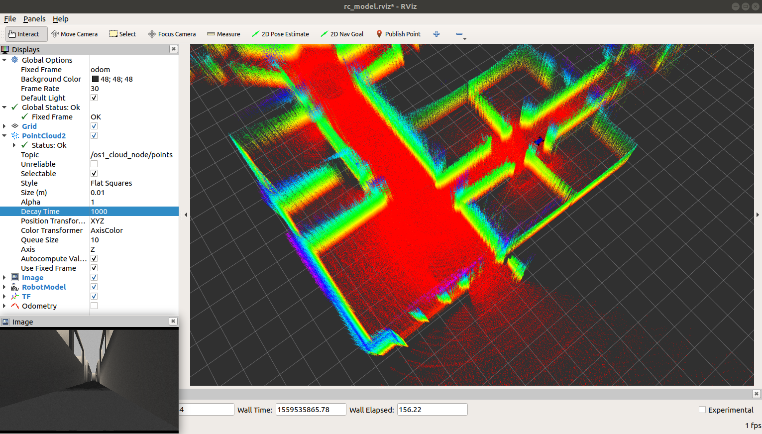
Once the odometry output is verified, similar systems and configurations can be used in a real-world system.
Odometry Estimation on an RC Car
Now that the odometry system is verified in simulation, we can integrate the robot_localization nodes into a complete robotic system. For this example, we will mount the OS-1-64 to an RC car platform. The system also has an OpenMV camera mounted but this isn’t used by the Cartographer system. The vehicle can be operated remotely with an Xbox controller. All processing is done on a fitlet2 with an Arduino Uno providing commands to the motors for steering and throttle. This set-up closely mimics the simulated system used earlier.
An image of the complete system is below:

When working with the RC car, the diy_driverless_car_ROS repository is used. When manually operating the RC car, the rc_dbw_cam.launch lauch file is used to start the system.
IMU Filtering
The OS-1 lidar IMU outputs angular velocities from the gyroscope and linear accelerations from the accelerometer, but it doesn’t publish traditional orientation values such as roll, pitch, and yaw. The sensor also has some inherent bias in the measurements which we need to account for.
The imu_complementary_filter package provides a filter which fuses angular velocities, accelerations, and (optionally) magnetic readings from a generic IMU device into a quaternion to represent the orientation of the device wrt the global frame. This work is based on the algorithm by Roberto G. Valenti etal. described in the paper “Keeping a Good Attitude: A Quaternion-Based Orientation Filter for IMUs and MARGs.”
The filter can also publish a tf frame which represents the estimated IMU orientation as well as the roll, pitch and yaw angles corresponding to the orientation published on the imu_data topic. These are helpful for debugging and are enabled by enabling the publish_debug_topics parameter.
The imu_complementary_filter is configured and executed in the rc_dbw_cam.launch file and publishes the filtered IMU data on the imu/data topic. The RViz IMU plugin can be used to visualize the orientation estimate. In the image below, the coordinate frame represents the estimated IMU orientation and you can observe it move as the OS-1 is rotated.
Laser Scan Matching
The RC car doesn’t have a GPS sensor to use for position estimates. Instead, the lidar data is used to estimate position. This position estimation is accomplished with the laser_scan_matcher package.
The laser_scan_matcher is an incremental laser scan registration tool. The package allows to scan match between consecutive LaserScan messages, and publish the estimated position of the laser as a geometry_msgs/Pose2D or a tf transform.
The laser_scan_matcher node can operate using sensor_msgs/LaserScan messages or sensor_msgs/PointCloud2 messages. We will use the pointcloud_to_laserscan node to convert the 3D PointCloud2 message from the lidar sensor to a 2D LaserScan message. This is because the current implementation of the laser_scan_matcher node only supports 10,000 rays, which is less than the OS-1 lidar produces. The pointcloud_to_laserscan node is configured in the pointcloud_to_laserscan.launch file.
The laser_scan_matcher node supports various inputs that can be used to speed up the scan registration process by providing a guess for the current position of the sensor every time a new scan message arrives. We will use filtered IMU data from the imu_complementary_filter node as an estimate for the change of the orientation angle (delta-theta) of the robot in the form of a sensor_msgs/IMU message.
Lastly, since the robot_localization package requires geometry_msgs/PoseWithCovarianceStamped input messages, we can enable the publishing of this message with the publish_pose_with_covariance_stamped parameter. The laser_scan_matcher.launch file contains the configuration parameters for the laser_scan_matcher node.
The laser_scan_matcher node can publish a tf transform which is useful for debugginb. The example tf tree is depicted below:

It’s also helpful to view the estimated position of the “base_link” frame with respect to the “odom” frame published by the laser_scan_matcher node. This requires the publish_tf parameter to be enabled in the laser_scan_matcher.launch file. We also temporarily disable the ekf_localization_node since it also published an “odom” frame tf message. We can review the performance of the laser_scan_matcher node when processing replayed data with the following command:
$ roslaunch rover_teleop rc_dbw_cam.launch replay:=true rviz:=true ekf:=false
The video below depicts the estimated vehicle trajectory using the laser_scan_matcher node. It works fairly well as the ending location of the robot is close to the initial position, as expected.
EFK Configuration
Now that we have geometry_msgs/PoseWithCovarianceStamped input messages from the laser_scan_matcher node and sensor_msgs/IMU messages from the imu_complementary_filter node, we can update the ekf_localization_node configuration. This is done in the racer_localization.yaml configuration file.
The primary changes from the simulation configuration are on the sensor input configurations. They are updated to match the new measurements from the imu_complementary_filter and laser_scan_matcher nodes.
For the IMU data, the topic name is updated to /imu/data but the rest of the configurations are the same.
imu0: /imu/data
imu0_config: [false, false, false,
true, true, true,
false, false, false,
true, true, true,
true, true, false]
imu0_differential: false
imu0_queue_size: 10
imu0_remove_gravitational_acceleration: true
Since the laser_scan_matcher node publishes a geometry_msgs/PoseWithCovarianceStamped message type instead of the nav_msgs/Odometry type published by the navsat_transform_node, the pose sensor prefix is used instead of odom. The topic name is updated but the configuration information remains the same.
pose0: /pose_with_covariance_stamped
pose0_config: [true, true, true,
false, false, false,
false, false, false,
false, false, false,
false, false, false]
pose0_differential: false
pose0_queue_size: 10
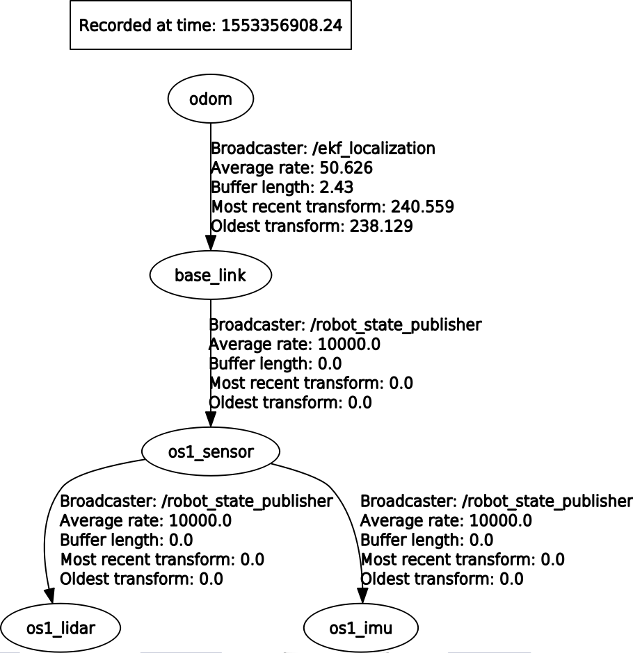
The ekf_localization_node publishes the “odom” tf transform as depicted on the TF tree below:
Again, we can replay recorded data to verify the performance of the ekf_localization_node.
The performance is similar to that of the laser_scan_matcher node in this example. However, one benefit of using the ekf_localization_node is that it publishes the odometry estimate as a nav_msgs/Odometry instead of the geometry_msgs/PoseWithCovarianceStamped message type that the laser_scan_matcher node publishes. The nav_msgs/Odometry message type is required for more advanced localization and navigation nodes such as the ROS Navigation stack.